VE7CNF - 630m Antenna Matching Using Just a Resistor
Links: PDF Version Detailed Version Web Detailed Version PDF VE7CNF Amateur Radio Pages
To tune and match a 630m-band transmitting antenna, my main tool is a resistor.
OK, the resistor isn’t actually used for matching, just for measurements. And you’ll need a few more things. You have to build a variometer to resonate the antenna, and a transformer to match it. You’ll also need a signal generator or low-power transmitter and an oscilloscope. Here’s the test setup and procedure:

1) At the base of the antenna, connect a reference resistor R1 (50 to 200 ohms non-inductive) and oscilloscope as shown above.
2) Apply 475 kHz from a signal generator or low-power transmitter, around 0.1 to 2W. It can be located indoors and connected by coax, or outdoors at the antenna.
3) Tune for resonance by adjusting the variometer inductance L until waveforms V1 and V2 are in phase. Usually V2 will drop to minimum at resonance.


Oscilloscope traces CH1 (V1)
and CH2 (V2, lower amplitude trace)
Screens are: L too high (left), L correct (middle, resonance), and L too low
(right)
4) Calculate the transformer input resistance R2 at resonance.
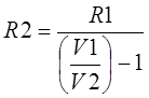
R2 = R1 / [(V1/V2) – 1]
V1 is the voltage measured
between the top of R1 and GND.
V2 is the voltage measured between transformer input and GND (across R2).
V2 is in phase with V1 at resonance, when R2 is resistive
5) Adjust the transformer turns ratio to give R2 = 50 ohms when the variometer is tuned for resonance.
6) Remove R1 from the circuit (short across it) and start full-power transmitting.
Measuring the Antenna Without a Transformer
Before you have a transformer, you can leave it out of the circuit and connect R1 directly to the variometer. Tune for resonance (minimum V2), then measure the voltages and calculate R = R1 / [(V1/V2) – 1] for the antenna itself. Then the transformer turns ratio you’ll need is:
N2 / N1 = √(R / 50)
One-Channel Oscilloscope
To find resonance, just measure V2 and tune the variometer for minimum voltage. You can then measure V1 and V2 separately and do the calculations. A 2-channel scope lets you find resonance more accurately.
Important Tips
Things are simplified if the reference resistor R1 = 50 ohms. In that case, you have achieved a match (R2 = 50 ohms) if V2 is half of V1. A 47 ohm resistor is more common and close enough.
For R1 use a non-inductive resistor (carbon, metal film, metal oxide etc. in the 1/4W to 3W power range). Values from 50 to 200 ohms usually work well. For 50 ohms try Panasonic ERG-3SJ510 or Vishay PR03000205109JAC00. A higher value is better for measuring R of a high-resistance antenna.
Measurements must be made right at the matching network near the base of the antenna. At the shack end of the coax, with any mismatch, the coax cable transforms the impedance so that you’re not measuring the actual antenna values.
When making AC measurements, it’s important to use x10 oscilloscope probes that have been properly compensated. Connect the probe ground clips to the transformer / radial ground.
Matching transformer design (core selection and the number of turns) is a separate subject, so do some web searching for details. If transformer winding inductance is not high enough, you have to de-tune the antenna slightly to leave some capacitance that cancels the transformer inductance.
I’ve used this method from 136 kHz to 2 MHz with good results.
Thanks for feedback from VA7MM and KA7OEI.
(c) Toby Haynes, VE7CNF. Dec, 2017