VE7CNF - 630m Transverter using a Bidirectional High-Power Mixer
Toby Haynes
October, 2016
(Home – VE7CNF Ham Radio Page)
(Link: PDF Version of Article)
I’ve developed a 630m band linear transverter that produces 30W of transmitter power. It has no power amplifier and draws only 175 mA from a 12V power supply. It works for both transmit and receive with no T/R antenna relays or switching circuits.
I’ve used a bidirectional high-power mixer circuit to directly take 100W of power from a 160m band transceiver and produce useful output power on 630m. For receive, 630m signals can pass backwards through the circuit and are up-converted to 160m.

Transverter Block Diagram
For the detailed schematic, see the PDF file: VE7CNF_Transverter_Schematic.

Transverter components connected for on-air testing

High-power mixer circuit handles 100W input power
The balanced mixer uses two power MOSFET switches to alternately connect either the inverted or non-inverted 160m signal to the output. Each switch uses two N-channel MOSFETs back-to-back so that their internal drain-source diodes can’t pass a signal when the MOSFETs are off. The switches turn on and off alternately at the 1.5 MHz local oscillator frequency.
Because the mixer is only switching the analog signals passing through, it works equally well in both directions. It requires no power supply, but it does require about 1.5 watts of square wave drive power into the MOSFET gates to turn them on and off at 1.5 MHz.
At the mixer output the difference frequency 475 kHz, sum frequency 3475 kHz, and other mixer products resulting from harmonics of the local oscillator are present. A diplexer passes the 630m signal (30 watts) to the antenna and directs unwanted frequencies (about 50 watts) to a dummy load resistor.
At the transceiver connector, another diplexer allows only 160m signals to pass between the transceiver and mixer. Signals coming from the mixer input port at other frequencies (about 10 watts while transmitting) are directed to a dummy load resistor.
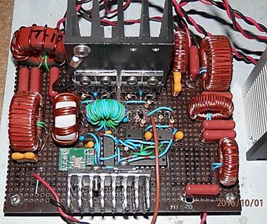
Transverter circuit on perf board
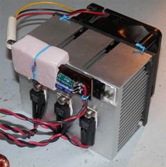
50 Ohm dummy loads mounted on a CPU cooler, with fan control circuit
This project started as an interesting design idea. In the end, it works great but it’s turned out not to be simple or cheap. There are a lot of toroid cores to wind. Diplexer and filter components and heat sinks have to be sized properly to handle the 100W transceiver power for long key-down periods in digital modes.


First prototype on plug board