VE7CNF – Lightwave Station
Toby Haynes VE7CNF
March, 2016
1 Contents
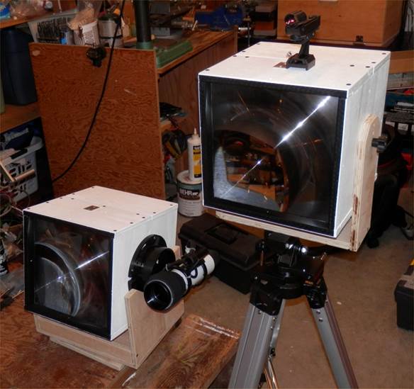
VE7CNF Lightwave Transmitter (left) and Receiver (right). Large plastic Fresnel
lenses are used, 260x260mm with focal length 200mm.
My lightwave station is based on the work of VE7SL, VE7CA, and VE7BDQ. See Steve’s excellent article in TCA magazine or the link on http://members.shaw.ca/skcraig/lightwave.html. I used their optical design. After a bunch of calculations, I found that they had come up with a pretty much optimized design giving optical beam widths of about 1 degree for the transmitter and receiver. The large Fresnel lenses with short focal length were an excellent choice.
For the electronics, I put together a system of my own that has a few extra parts. For future experiments I wanted the ability to change the transmit LED and driver, and use different PIN diode detectors and preamplifiers. In the future I’d like to put the receiver onto my astronomical telescope to hear what’s “out there.” I may experiment with infrared wavelengths, and with using modulated subcarriers for communication.
I added the ability to modulate the transmit LED with the audio output of a PC, and to bring line level audio from the receiver into a PC. That allows for digital communication modes like RTTY, JT9, and MFSK.
Lightwave Transmitter
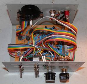
Lightwave Transmitter Exciter and LED Driver


Lightwave Transmitter Exciter. Includes CW keyer and beacon generator for normal
CW speeds and QRSS. Accepts audio from a PC for transmitting digital modes.
RS232 interface to a PC for remote control.
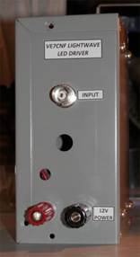
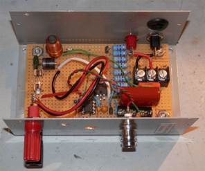
Lightwave LED driver. A MOSFET switches square wave current through the
transmitter LED.
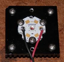
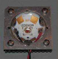
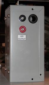
1W Deep red LED on heat sink, with converging lens to direct all the light onto
the Fresnel lens.
The transmit LED assembly slides forward/backward to focus, then 3 screws lock
it down.

The azimuth bearing uses 3 furniture sliders on the base and a bumpy formica
sheet on the rocker box, with a 1/4-20 bolt through the center.
Dobsonian style alt/az transmitter mount uses ABS toilet flanges for the
altitude bearings. In the field this sits on a sturdy folding work table. The
finder scope assembly is borrowed from a telescope.
Lightwave Receiver
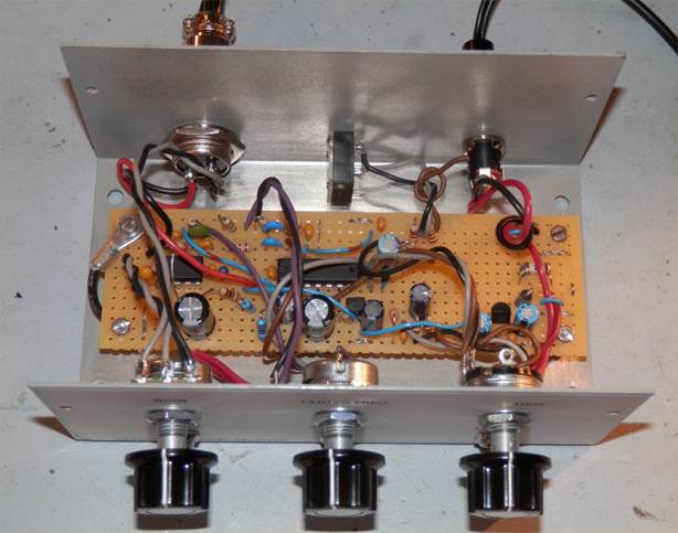
Lightwave receiver. Includes audio amplifier, tunable bandpass filter,
headphone amplifier and line level output to PC for digital modes.
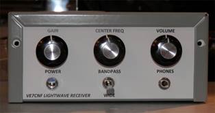
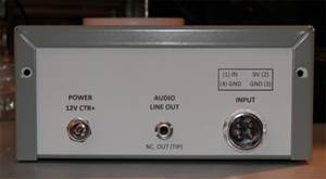
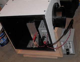
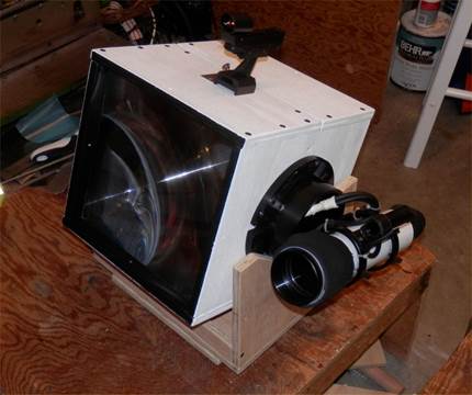
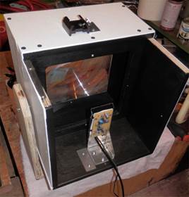
Lightwave receiver
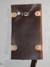
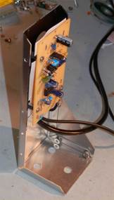
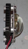
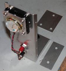
PIN Photodiode detector/preamplifier board and holder assembly.
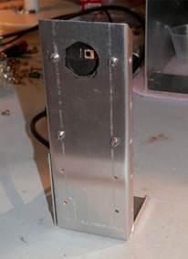
Detector mounted in the receiver box. Right photo shows metal shield over the
circuit board.
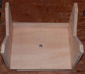
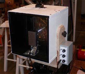
A wooden fork holds the box, and two 1/4-20 bolts form an altitude bearing. The box is tilted as required, then locked by the bolts. The receiver sits on a Celestron “Heavy Duty Alt-Azimuth” tripod that has two adjustment knobs for fine pointing.
A SkyWatcher “Red Dot Finder” is mounted on top of the box. It has fine alt and az adjustment screws to align it with the receiver optics. Standing a couple of feet behind the box, you look into the distance with both eyes, with one eye also looking through the finder. It superimposes a red dot on your view to show where the receiver is aimed.