VE7CNF - A Spark Gap Transmitter with a Pure Note
VE7CNF Amateur Radio Pages http://phasordesign.com/VE7CNFamateurRadio
Introduction
Wireless telegraphy began with spark gap transmitters in the 1890’s. They are a simple device that produces repetitive radio-frequency pulses of significant power. In late 2001, prompted by the 100th anniversary of Marconi’s first transatlantic transmissions, I did some research into spark gap transmitters. That investigation rekindled my interest in the amateur radio hobby after a 15 year break. Since then I’ve thought about building a spark gap transmitter myself, to gain hands-on knowledge of the early technology.
It has not been legal for a radio amateur to connect a spark gap transmitter to an antenna since 1924. However, any circuit can be tested while connected to a dummy load. Some stray emissions from a spark gap running in my workshop will add little to the strong radio noise that I measure around my home. On MF and HF I hear a 180 Hz buzz from nearby power lines and noise from the neighbour’s heat pumps, appliances, TVs, chargers, etc.
Powerful spark gap transmitters were built using high voltage transformers and rotating spark gaps. I chose to hook up a simpler transmitter using an auto ignition coil and a fixed spark gap. My goals were to see how much output power could be produced by the simple circuit, and how pure a transmitted note could be achieved.
I hooked up a prototype circuit that produces a peak pulse power of 260 W into a dummy load. That sounds impressive, but the average power is only 1.6 W. DC input power is 37 W, so the efficiency is only 4.3 %. The 340 Hz note is quite pleasant.
MP4 Video Link: Spark gap in action
WAV Audio Link: Signal on an AM receiver The transmitter was loosely coupled to produce 6W output pulses into a string of attenuators that connected to the receiver through coax.
Back in the beginning, the men of wireless spoke of wave length, condensers, aerials...
Spark Gap Circuit

Spark Gap Transmitter Circuit
The circuit shown produces bursts of 631 meter waves that repeat at an audible rate of 340 cycles per second. A wireless receiver hears this as a note of medium pitch that one would describe as a “buzz.” The note is rich in harmonics and has small variations in amplitude and period caused by the random nature of the spark. The note sounds “pure” when the random variations are minimal.
The circuit was put together in a temporary fashion with the parts placed on a wooden table and interconnected using wires with clips. No aerial is connected to this circuit. Instead, the circuit includes an aerial condenser CA that takes the place of an aerial’s capacity. An aerial resistance RA takes the place of the radiation and losses that an aerial would provide, and a small shunt allows the aerial circuit current to be measured.
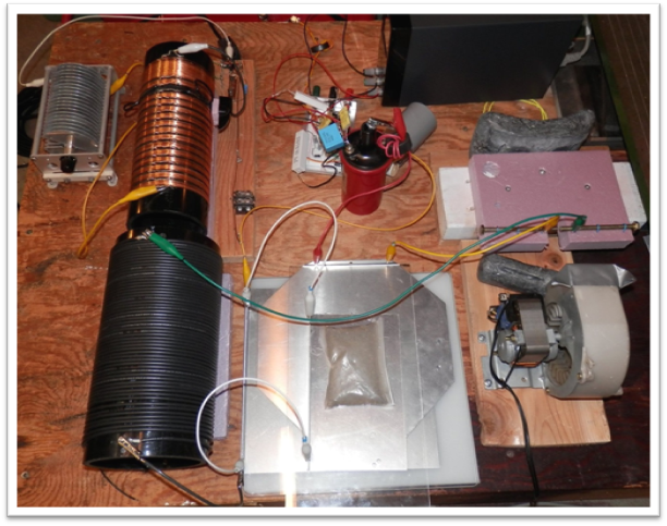
Spark gap transmitter. Top center: Induction coil and primary switch. Lower
right: Spark gap and blower. Bottom center and left: Primary condenser and coil.
Top left: Aerial condenser and coil.
To create sparks, the primary switch Q is made to close repeatedly for short intervals of less than 1/640 second by a control wave repeating at the note pitch of 340 cycles per second. On each closing, the battery voltage is applied to the induction coil’s primary winding and the current rises to 5.5 amperes. When the switch opens, the induction coil’s secondary voltage rises rapidly to charge the primary condenser C.

Primary condenser (0.82 jar) is made from 3 aluminum sheets and 2 glass
sheets
When the condenser voltage is high enough it initiates a spark in the gap. The gap can then carry current with low resistance as long as the spark is maintained by some current flow. The spark gap is formed by two steel bolts with their ends separated by 1/10 inch. The spark acts as a switch that connects the condenser C to the primary inductance L to complete the primary circuit, which then oscillates with 631 meter waves of high current for a short time. After about 10 waves most of the primary alternating current is lost.
Spark gap in operation
Primary circuit current shows the 631 meter wave that lasts a short time for
each spark.
The aerial inductance LA is coupled to the primary inductance L by some mutual field. The aerial condenser CA and inductance LA form an oscillating circuit, also with a wave length of 631 meters, which conducts current through the aerial resistance RA of 50 ohms and the shunt.
If the aerial capacity CA is small, so that a large aerial inductance LA is required, then the 631 meter wave lasts a long time and occupies a narrow span of wave lengths. In this situation the voltage on an aerial can be very high and cause brushing, or in this case flashover in the aerial condenser.
Flashover occurs in the aerial condenser when the capacity is small and
coupling is tight.
Mutual coupling between the inductances was loosened so that no flashover occurred. Aerial circuit current was less than what is possible if a condenser with wider spacing were used. With the aerial capacity CA set to 0.07 jar the maximum aerial circuit current is 1.03 amperes and so the power into the aerial resistance RA is 52 watts. The average power, however, is very low because the 631 meter waves occur for a very small proportion of the time. Average power is 0.43 watt.
Aerial circuit current reaches 1.03 amperes with small aerial capacity of
0.07 jar. Power peaks at 52 watts and the average is 0.43 watt. The 631 meter
wave lasts much longer than it does in the primary circuit.
Aerial circuit current with small aerial capacity occupies a small span of
wave lengths.
As the aerial capacity CA is made larger, a smaller aerial inductance LA is needed, the aerial voltage is lower, and aerial circuit current is greater. The 631 meter wave lasts for a shorter time and occupies a greater span of wave lengths. With the aerial capacity CA set to 0.23 jar the maximum aerial circuit current was 2.3 amperes and so the power into the aerial resistance RA was 260 watts. The average power is much smaller, only 1.6 watts.
Aerial circuit current reaches 2.3 amperes with large aerial capacity of
0.23 jar. Power peaks at 260 watts and the average is 1.6 watts. The 631 meter
wave has higher current but lasts for a shorter time than with lower aerial
capacity.
Aerial circuit current with larger aerial capacity occupies a larger span of
wave lengths.
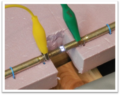
The qualities of the spark affect the purity of the note. After each spark, it is desirable to clear the spark gap of all byproducts of the arc before the next spark, so that all new sparks form in the gap at a consistent voltage. This minimizes random variations in the amplitudes and times of the 631 meter waves. Placing the spark gap in a stream of flowing air clears it and results in a pure note. The rate of sparking should not be too high so as to allow time for the gap to be cleared. It is for this reason that a rate of 340 cycles per second was chosen. Higher spark rates did not produce as pure a note.
Spark gap with blower. The blower clears the gap after each spark to give a pure
note.
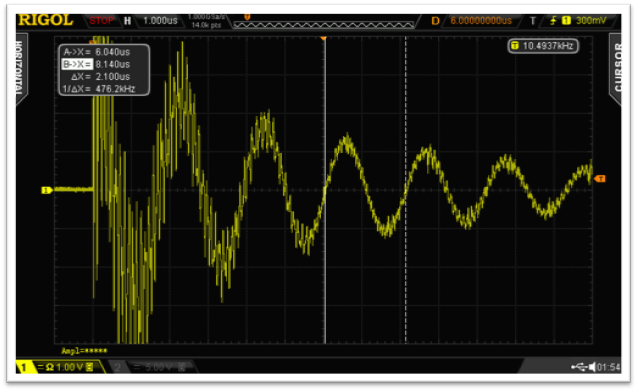
On each cycle of the control wave for the primary switch, one spark occurs and one brief pulse of oscillating waves is produced in the aerial circuit. These repeating pulses produce a note in a receiver, and the note is pure if the amplitude and timing of the pulses are steady.
A pure note with the blower running. 631 meter wave current and timing are
consistent.
Top: 631 meter waves in aerial circuit.
Bottom: Primary switch control wave at 340 cycles per second, with interference.
MP4 Video Link: Spark with the blower running
The effect of removing the stream of air from the spark gap is to produce large variations in the amplitude and times of the 631 meter waves, and so produce a very poor note.
A poor note with the blower off. 631 meter wave current and timing vary
randomly.
Top: 631 meter waves in aerial circuit.
Bottom: Primary switch control wave at 340 cycles per second, with
interference.
MP4 Video Link: Spark with the blower off
Results
A note of high purity was achieved by using just enough induction coil primary current to produce a reliable spark, selecting the right metal for the spark gap, and using an air blower to clear the gap between sparks.
Maximum aerial circuit current of 2.3 amperes was achieved in a 631 meter wave, which gives a maximum power of 260 watts in the aerial resistance of 50 ohms. The average power, however, is only 1.6 watts because the 631 meter wave lasts a very short time. The transmitter draws 37 watts of power from the battery.
Here are some details of the transmitter:
Battery 24 volts at 1.55 amperes average
Spark rate 340 cycles per second
Induction Coil MSD Blaster 2
Primary current 5.5 amperes after 1/640 second with primary switch closed
Spark Gap Gap width 1/10
inch
Two 1/4 inch diameter steel blots, grade 8 plated with yellow zinc
Ends beveled with a grinder to remove plating and sharp edges
Primary Condenser C Capacity 0.82 jar (910 mmf)
2 lass insulation sheets 0.23 and 0.09 inch thick
3 Aluminum sheets 0.040 in thick, approx. 8.5x8.5 in. bottom and center,
7x4 in. top. Center sheet is high voltage, outer sheets are connected together
Lower plastic base insulator 0.375 in thick.
Primary Inductor L 124 microhenries
56 turns #14 stranded insulated wire 8 in long on a 4-1/2 in dia. black ABS
pipe
Aerial condenser Air variable condenser
with gaps 0.075 in.
Capacity used was 0.07 to 0.23 jar (77 to 250 mmf)
Aerial Inductance 180 turns #24 enameled
wire 7-1/4 in long on a 3-1/2 in dia. black ABS pipe
All 180 turns gives 1460 microhenries. 80 turns gives 450 microhenries.
Aerial current at low capacity of 0.07 jar (77 mmf)
Peak
of aerial current 1.03 amperes
Current drops to 1/10 of peak after 0.000,085 seconds
Peak power 52 watts into the 50 ohms aerial resistance
Average power 0.43 watt
Aerial current at high capacity of 0.23 jar (250 mmf)
Peak
of aerial current 2.29 amperes
Current drops to 1/10 of peak after 0.000,040 sec.
Peak power 262 watts into the 50 ohms aerial resistance
Average power 1.57 watts
Lessons Learned
The spark gap transmitter looks straight forward to get going. That was not the case. Effort and experimentation were required, and a number of primary switch devices were destroyed while trying to produce energetic sparks from the induction coil.
When switch Q opens there is momentarily a high voltage across the switch from the primary of the induction coil. If the secondary is shorted or the spark gap is too small then that voltage becomes high enough to damage the switch device. A protection circuit was added across the switch to shunt current if the voltage exceeds 500. A fuse is required to protect the battery and the induction coil from a failed switch.
Details of the induction coil primary circuit switch
Voltage across primary switch Q. After the switch opens there is momentarily
over 260 volts across the switch.
Finding suitable spark gap material took some experimentation. As the gap width was increased the gap materials began to fail quickly. Brass was reliable for only a few seconds before sparks ceased. Stainless steel lasted somewhat longer. Steel drill bits worked well for small gaps but became hot with wider gaps. Success was found with 1/4 inch diameter grade-8 bolts which are made of medium-carbon steel, quenched and annealed. The ends were beveled with a grinder to remove plating and sharp edges. These have proven very reliable over time and they do not warm significantly. Others report success with tungsten welding rods.
The induction coil primary switch should close for just long enough on each spark cycle to reliably initiate a spark in the gap after it opens. This gives the purest note. If the primary switch is closed for too long, the spark becomes too hot and the note is poor.
In the primary condenser, the aluminum surfaces on either side of the 0.09 inch glass sheet have become discolored, while surfaces in contact with the 0.23 inch glass are clean. There may be brushing occurring on the aluminum surfaces against the thinner glass. Thick glass should be used for all layers.
To adjust the transmitter, first set the spark gap width as desired from about 1/20 inch to 1/10 inch. A larger gap gives higher aerial circuit current. Set the primary switch closure time to be just long enough to give a consistent spark. Adjust the main condenser C by sliding the top aluminum plate, so that the primary circuit current is a 631 meter wave. Adjust the aerial condenser for maximum aerial circuit current. Check the wave length and repeat adjustments of the primary and aerial condensers as needed. Aerial circuit current may be adjusted by changing the inductor coupling, but loosen coupling if brushing occurs.
During operation, touching the connection between the aerial condenser and aerial inductance is mildly painful and causes a small burn. I have not experienced touching the primary circuit.
To best hear the signal from a spark gap transmitter, an amateur receiver should be set up to detect amplitude modulation. All noise rejection circuits must be disconnected.
More Work
Higher aerial circuit current might be achieved if the capacity of the primary condenser is increased and the primary inductance is decreased. There are possible problems with this. If the capacity is too high then the induction coil would be unable to raise the voltage enough to initiate a spark in the gap. Also, the spark may be hotter and result in a poor note.
The primary and aerial inductance coils were borrowed from other projects and are not ideal. Coils wound with heavier gauge wire would have lower loss. With such coils, the aerial circuit current would probably be higher and the span of wave lengths would be smaller.
An aerial condenser with wider plate spacing would allow for higher voltage without sparking. This would permit tighter coupling to be used at low aerial capacity, and so achieve a high aerial circuit current that would occupy a narrow span of wave lengths.
(c) Toby Haynes VE7CNF. April 2018