VE7CNF - Condenser No. 7 Patt 2486 A
PDF Version http://phasordesign.com/VE7CNFamateurRadio/CondenserNo7/VE7CNF_CondenserNo7.pdf
Web page http://phasordesign.com/VE7CNFamateurRadio/CondenserNo7/VE7CNF_CondenserNo7.htm
VE7CNF Amateur Radio Pages http://phasordesign.com/VE7CNFamateurRadio
Condenser No. 7 on top of a VF-1 VFO and beside an 813 tube.
A couple of years ago I came across a unique variable condenser, apparently very old, for sale at a hamfest. The faceplate said “Jars. Condenser No. 7.” It had a lot of brass, a thick bakelite panel and knob, and a glass cover jar with a white rubber seal. There was a war assets tag attached. It was in rough shape but the $20 price was right so I bought it.
Condenser No. 7 Before restoration.
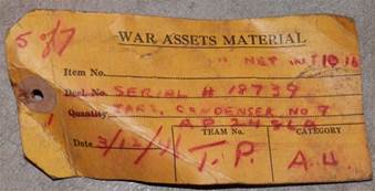
War assets tag and label from shipping box.
There was significant corrosion. The bakelite was dirty and dull with various chips. The rubber seal was cracked and bonded to the glass. Inside the glass were particles of failed rubber and some kind of creeping rot. I feared further corrosion would damage the brass parts.
Online I found a little information related to the “Condenser No. 7.” and a few photos. I found only one photo of the equipment that the condenser was used in, and no references to museum displays of such equipment.
“Jars” does not refer to the manufacturer, but rather to an old unit of capacitance. The condenser’s scale reads from 0.05 to 0.95 Jars. According to Wikipedia, “A jar was an early unit of capacitance once used by the Royal Navy. The term originated as the capacitance of a Leyden jar. Its value is such that one farad is 9×10^8 jars and one jar is 1111 picofarads.” (ref [1]).
The Condenser No. 7 was part of the Royal Navy’s Model “C” antenna tuning circuit used for radio reception on ships in the spark era. According to one reference [3], this tuner was designed and improved from 1910 to 1912. A document from 1924 (ref [2]) describes the tuner’s operation. The Model “C” was a collection of inductors, capacitors, and switches that could tune the antenna for wavelengths from MF/LF to VLF, about 200 m to 19,000 m. Originally it provided a signal to a detector that used a galena crystal. Later receivers used tubes. A schematic of the Model “C” shows three Condenser No. 7’s in the circuit (ref [2]). A diagram of a ship’s receiver system shows two Model “C” circuits feeding two receivers (ref [2]).
Schematic of Tuner Model “C” (ref [2]) shows three of Condense No. 7. The
patent number on this diagram does not match mine (2486 A). It is shown to be
the same as Condenser No. 13, so may be wrong.
A Radio Cabinet (ref [3]). Parts 5 and 15 appear to be Condenser No. 7.
Part 4 should be also, according to schematics, but the scale colouring is
different.
I put a couple of days into the cleanup. Old shellac and corrosion were removed from the brass. The bakelite was cleaned, missing chips repaired, and the scale re-painted. Shellac on most capacitor plates was still in pretty good shape but I re-coated a few. The old rubber seal was cut out and replaced with neoprene foam. Everything was buffed and coated with conservator’s wax. I’m sure the shine won’t last and I’ll be polishing it again in a few years.

Condenser No. 7 After restoration.
This condenser is a piece of radio history from the era of the spark gap. It’s a beautiful thing to look at, as has not been made in a long time. I’ll be mounting it on a wall plaque for my office. Occasionally it’ll be put into active service in a replica 1920’s ham radio transmitter, to again be used for communication through the luminiferous aether.
Specifications
Panel 6-7/8
in. x 6-7/8 in., 5/8 in. thick, bakelite
Capacitance scale 0.05 to 0.96 Jars (56 to 1055 pF) on a bakelite plate 6
in. diameter
Depth from rear mounting surface 4.5 in. to faceplate, 5-3/5 in. to front of
knob
Knob 2-1/2 in. diameter bakelite.
Rear brass ring 6-7/8 in. diameter
Mounting holes 6-1/4 in. square pattern, 1/4 in. diameter holes,
countersunk for flathead screws with 0.45 in. diameter heads
Weight 4.3 kg (9 lb 7 oz)
Capacitor has 13 stator and 13 rotor plates, all 5-1/2 in. diameter, brass
coated with laquer
Three brass binding posts 0.233 in. diameter with 11/16 in. diameter brass
thumbnuts
Posts from left to right are rotor, stator, and knife-switch to stator.
More Schematics
The references include some schematics of the old equipment. It’s interesting to see how things were done. It probably took considerable skill to get everything tuned up.
Another tuner schematic. “Normal” is LF/MF, “Rugby” is VLF 16 kHz. Parts 4,
5, and 15 appear to be Condenser No. 7. Parts 17 through 22 appear to be a tube
receiver. (ref [3]).
Older receiver uses redundant galena crystals and bias batteries to increase
sensitivity. (ref [2])
Acceptor circuit (ref [2]). There should be a wire going right from pin 1 of
the “Acceptor Condenser.” See fig 15 below.

Radio cabinet wiring with two tuners (ref [2]). Antenna and earth
connections are at top center.
References
[1] https://en.wikipedia.org/wiki/Jar_(unit) Jar (unit)
[2] http://www.rnmuseumradarandcommunications2006.org.uk/CommsColLeft/Receivers/134%20Proper/pdfs/proper.pdf
O.U. 5327 (3) W/T Receiving Handbook, Chapter 3, Tuners. Admiralty Signal
Department. August 1924.
[3] http://www.rnmuseumradarandcommunications2006.org.uk/CommsColLeft/Receivers/receivers.htm
Receivers. HMS COLLINGWOOD HERITAGE COLLECTION.
Toby Haynes, VE7CNF. Mar, 2018